
Rigid-Flex PCB Manufacturer in USA
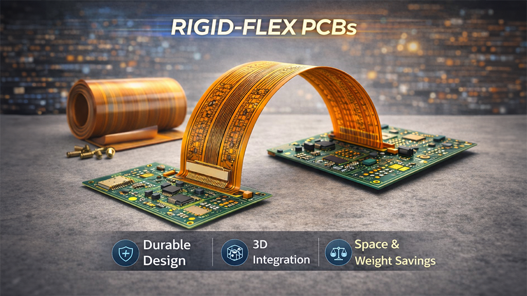
At CircuiTek Solutions, we produce Rigid-Flex hybrid printed circuit boards that combine rigid FR-4 sections with flexible polyimide circuitry in a single integrated build. Rigid-flex PCBs are designed for compact, space-constrained electronics where reliability, weight reduction, and 3D routing are critical.
Rigid-flex technology eliminates many connectors and cables found in multi-board assemblies, improving reliability and simplifying system design.
What Is a Rigid-Flex PCB?
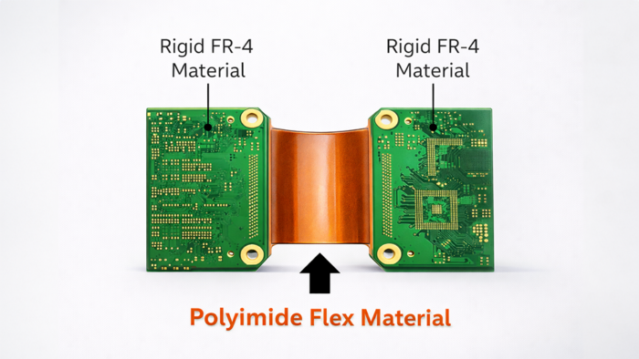
A rigid-flex printed circuit board is a single PCB construction that integrates:
- Rigid circuit sections for mechanical stability and component mounting
- Flexible circuit sections for folding, bending, and interconnection
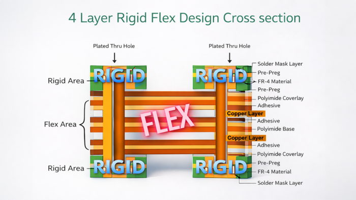
During fabrication, flexible layers are laminated between rigid layers using controlled heat and pressure. This creates an integrated structure that supports complex geometry while maintaining electrical and mechanical performance.
Rigid-flex boards can be built in custom stackups such as:
- 4-layer rigid-flex constructions
- 8- or 10-layer rigid-flex designs with embedded flex layers
- 12-layer rigid-flex structures with thermal management features
- 14-layer and higher rigid-flex builds based on application needs
Key Features of Rigid-Flex Printed Circuit Boards
Rigid-flex PCBs combine the advantages of rigid PCBs and flex circuits into one structure.
Key features include:
- Enhanced reliability by reducing connectors and solder joints
- Strong mechanical durability under vibration and motion
- Compact 3D design capability for space-saving assemblies
- Stable electrical performance across rigid and flex sections
- Support for complex multilayer interconnects
- Built-in thermal strategies for demanding environments
Materials Used in Rigid-Flex PCB Manufacturing
Rigid-flex PCBs use different materials in the rigid and flexible sections, plus specialized bonding and protective layers.
Core Material Types
Common material families include:
- FR-4 and high-TG FR-4 for rigid sections
- Polyimide (PI) films for flexible sections
- Copper foil for conductive traces and pads
- Coverlay and flexible soldermask systems for protection
Supporting Materials
Additional build materials often include:
- Adhesives and bonding films (including adhesiveless PI in some designs)
- Stiffeners for connector and mounting zones
- Silkscreen for labeling and assembly reference
- Surface finishes to protect copper and support solderability
Common surface finishes include:
- ENIG
- ENEPIG
- Immersion Tin
- Immersion Silver
- Hard Gold Fingers
- OSP
Technical Structure and Characteristics of Rigid-Flex PCBs
Rigid-flex boards are engineered to support both mechanical stability and controlled flexing.
Key technical characteristics include:
- Embedded flex substrates within a multilayer rigid stackup
- Via interconnects linking rigid and flex layers
- Controlled bend radius requirements for reliability
- Material compatibility management across rigid and flex zones
- Sequential lamination processes for complex builds
- Options for HDI features including blind/buried vias and microvias
Rigid-flex designs typically range from 4 layers up to 20 layers, depending on routing density and functional requirements.
Typical Rigid-Flex Specifications
Rigid-flex PCB specifications vary by application, but the following are common ranges:
Layer counts
4 to 20 layers
Materials
FR-4 + Polyimide (PI)
Board thickness
0.2 mm to 3.2 mm
Copper weight
application-specific, typically 0.5 oz to 3 oz inner
Surface finishes
ENIG, ENEPIG, Immersion Silver, Hard Gold, OSP
Technology options
controlled impedance, shielding, HDI via structures
Advantages of Using Rigid-Flex PCBs
Rigid-flex PCBs offer benefits that are difficult to achieve with separate rigid boards and cables.
Advantages include:
- Space savings through foldable 3D configurations
- Reduced system weight compared to multi-board assemblies
- Improved reliability by eliminating connectors and wiring harnesses
- Better resistance to vibration and mechanical shock
- Simplified assembly with fewer interconnect steps
- Support for high-speed routing and controlled impedance design
Rigid-flex becomes especially valuable when devices must be compact, durable, and reliable across long service lifetimes.
Applications of Rigid-Flex Printed Circuit Boards
Rigid-flex PCBs are used in electronics where space constraints and reliability requirements are high.
Applications include:
-
Consumer electronics
such as smartphones, wearables, and compact devices
-
Automotive systems
including ADAS, infotainment, lighting, and safety modules
-
Aerospace and aviation electronics
exposed to wide temperature ranges
-
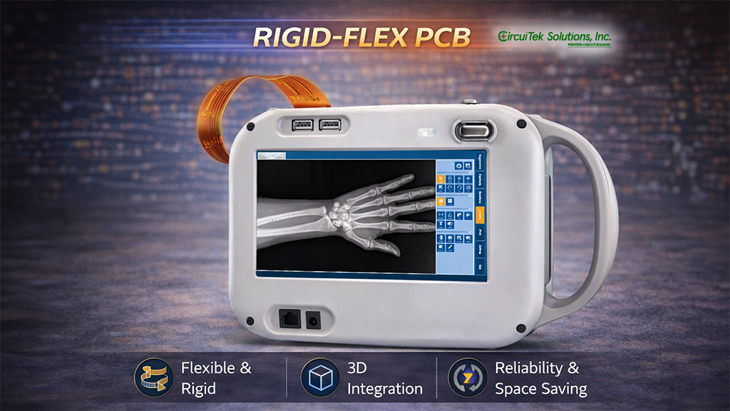
Medical implants
and compact medical devices
-
Defense and military systems
requiring rugged, lightweight designs
-
Industrial equipment
involving motion, rotation, or mechanical movement
Rigid-flex is also used in high-speed digital equipment, RF and microwave systems, instrumentation, and power electronics.
Why Choose Circuitek Solutions Inc. for Rigid-Flex PCB Manufacturing?
Circuitek Solutions Inc. is a trusted Rigid-Flex PCB manufacturer in USA, supporting complex rigid-flex programs from engineering through production.
We specialize in:
- Hybrid and mixed dielectric rigid-flex designs
- Sequential lamination and multilayer stackups
- Controlled impedance and high-density routing support
- Blind and buried vias, microvias, and via fill options
- Depth control drilling and back drilling
- Edge plating and specialty mechanical processes
- Prototype through low, mid, and high-volume production
Our process focuses on precision manufacturing, IPC-aligned practices, and reliable delivery for performance-critical rigid-flex applications.
EEAT-BASED & SEARCH-DRIVEN
Rigid-flex is preferred when space is limited and reliability is critical, because it reduces connectors and wiring while enabling 3D folding configurations.
Rigid-flex boards commonly range from 4 to 20 layers depending on routing density, stackup complexity, and application requirements.
By eliminating many connectors and cable assemblies, rigid-flex reduces failure points and improves performance under vibration and mechanical stress.
Yes. Bend radius, flex zone routing, layer transitions, and material compatibility must be engineered carefully to avoid fatigue and ensure long-term performance.